Our basic guidelines for sheet metal fabrication include important design considerations to help improve part manufacturability, enhance cosmetic appearance, and reduce overall production time.
Size
Maximum Dimensions
MM
IN
SIZE
1,016mm x 1,219.2mm
40 in. x 48 in.
LENGTH
1.219m
4 ft.
Minimum Dimensions
MM
IN
FLAT PART
12.7mm x 12.7mm
0.5 in. x 0.5 in.
FORMED PART
38.1mm x 38.1mm
1.5 in. x 1.5 in.
Tolerances
Single Surface
SIZE
LENGTH
1,016mm x 1,219.2mm
1.219m
Multiple Surfaces
MM
IN
FEATURES SEPARATED BY TWO OR MORE BENDS
1,016mm x 1,219.2mm
40 in. x 48 in.
Tolerances vary on depending on part feature such as bends, offsets, holes, and inserted hardware.
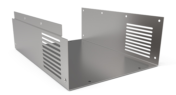
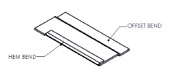
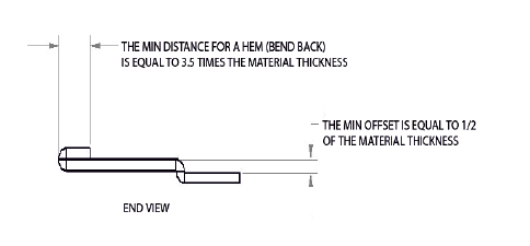
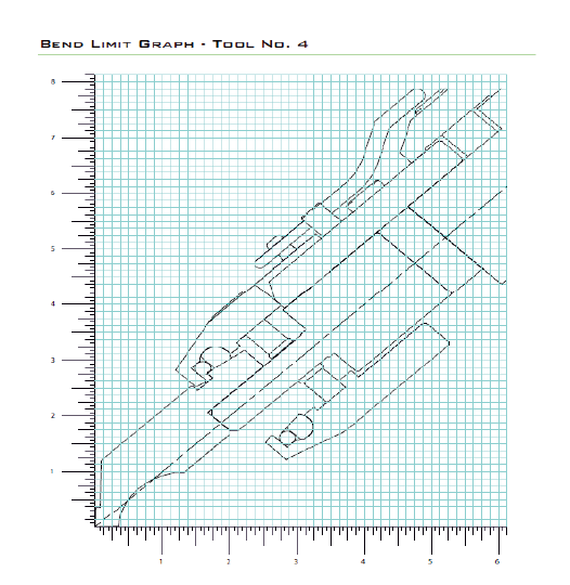
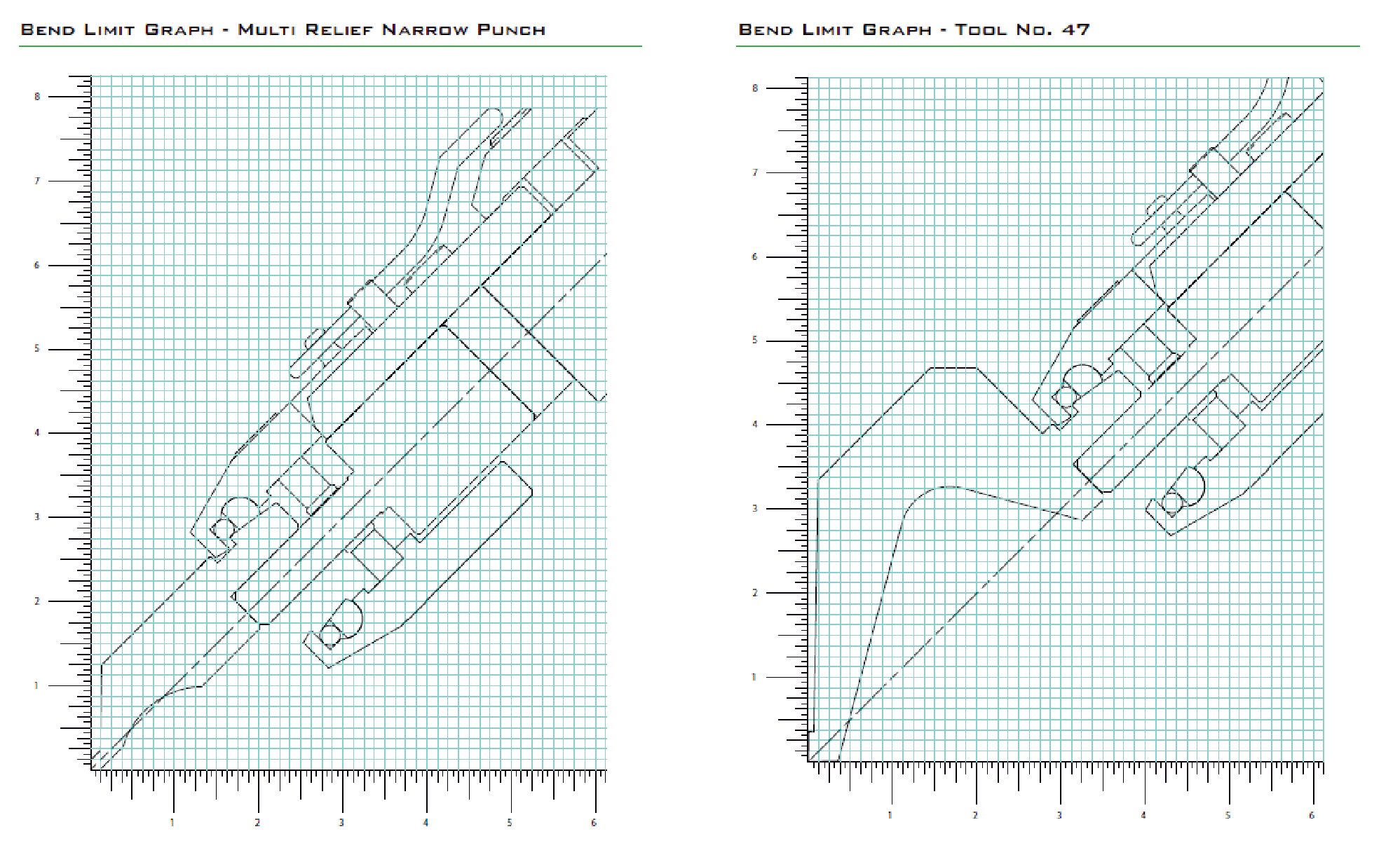
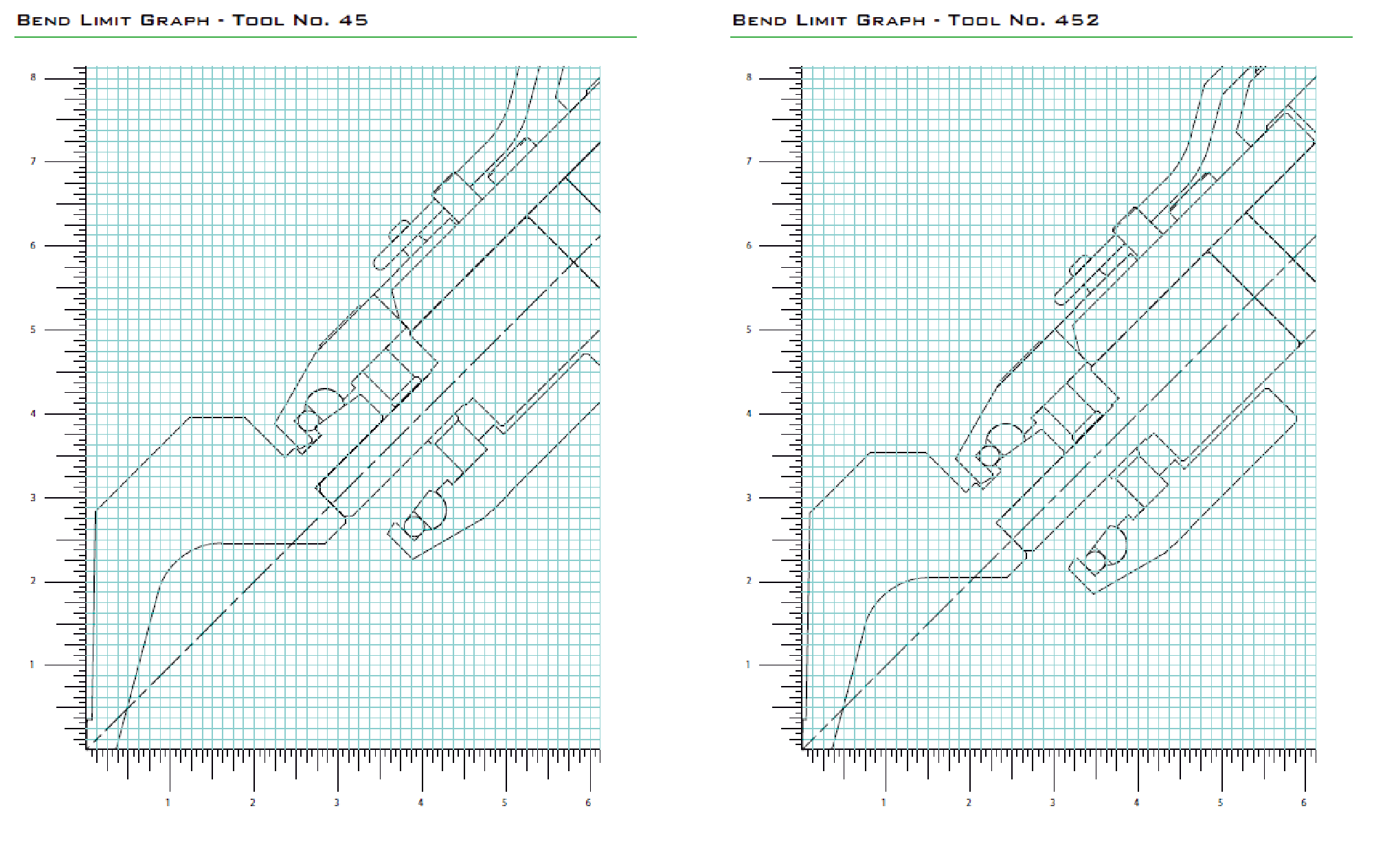
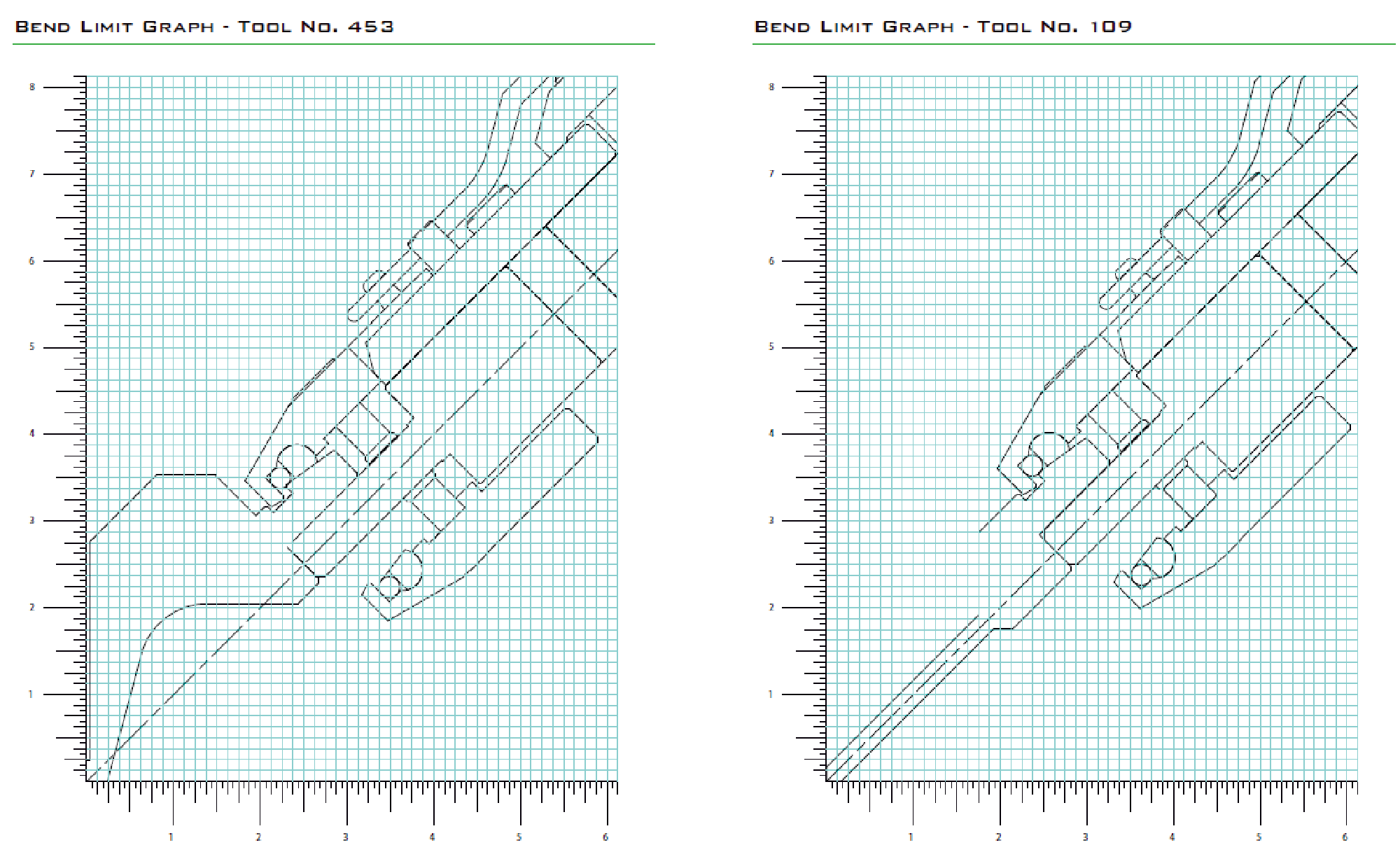
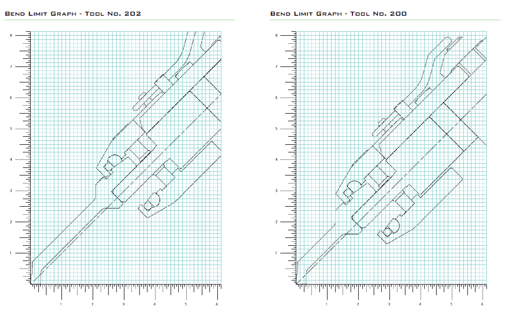
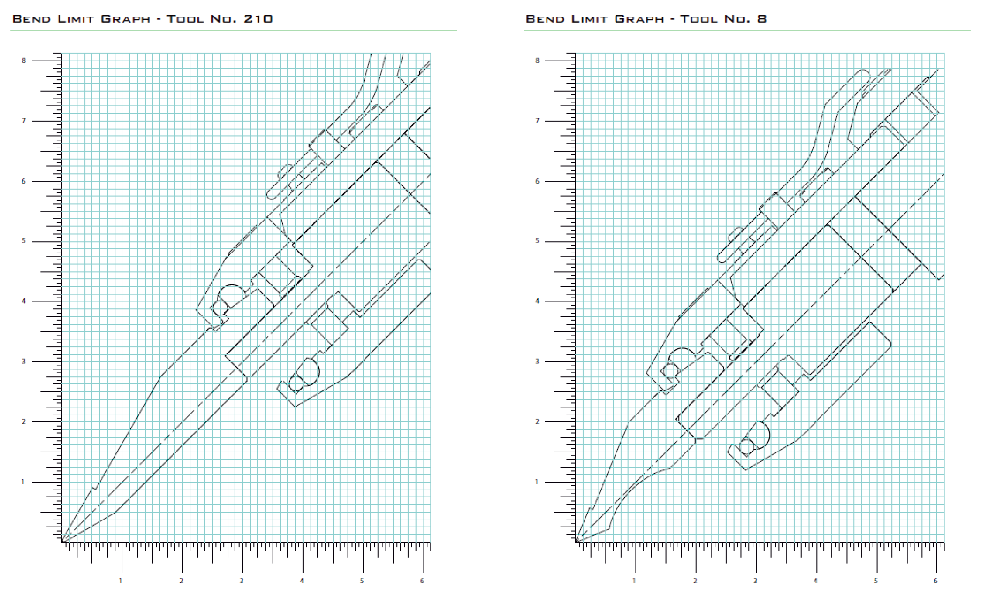
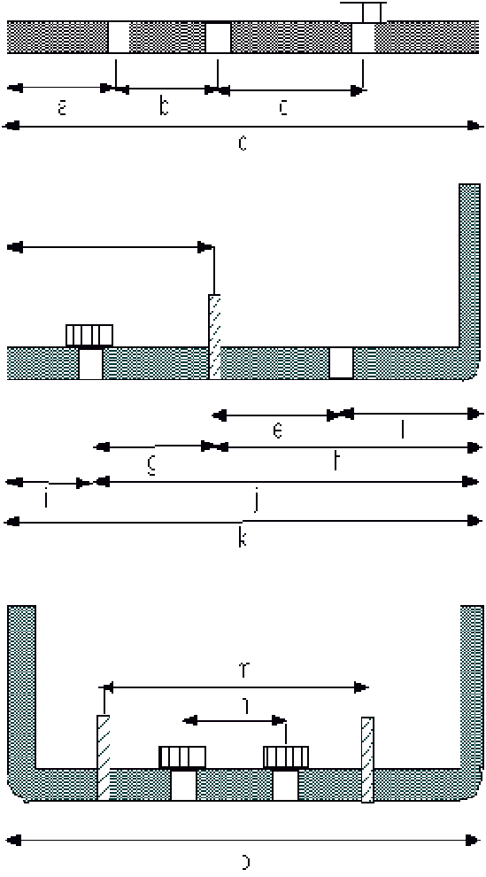
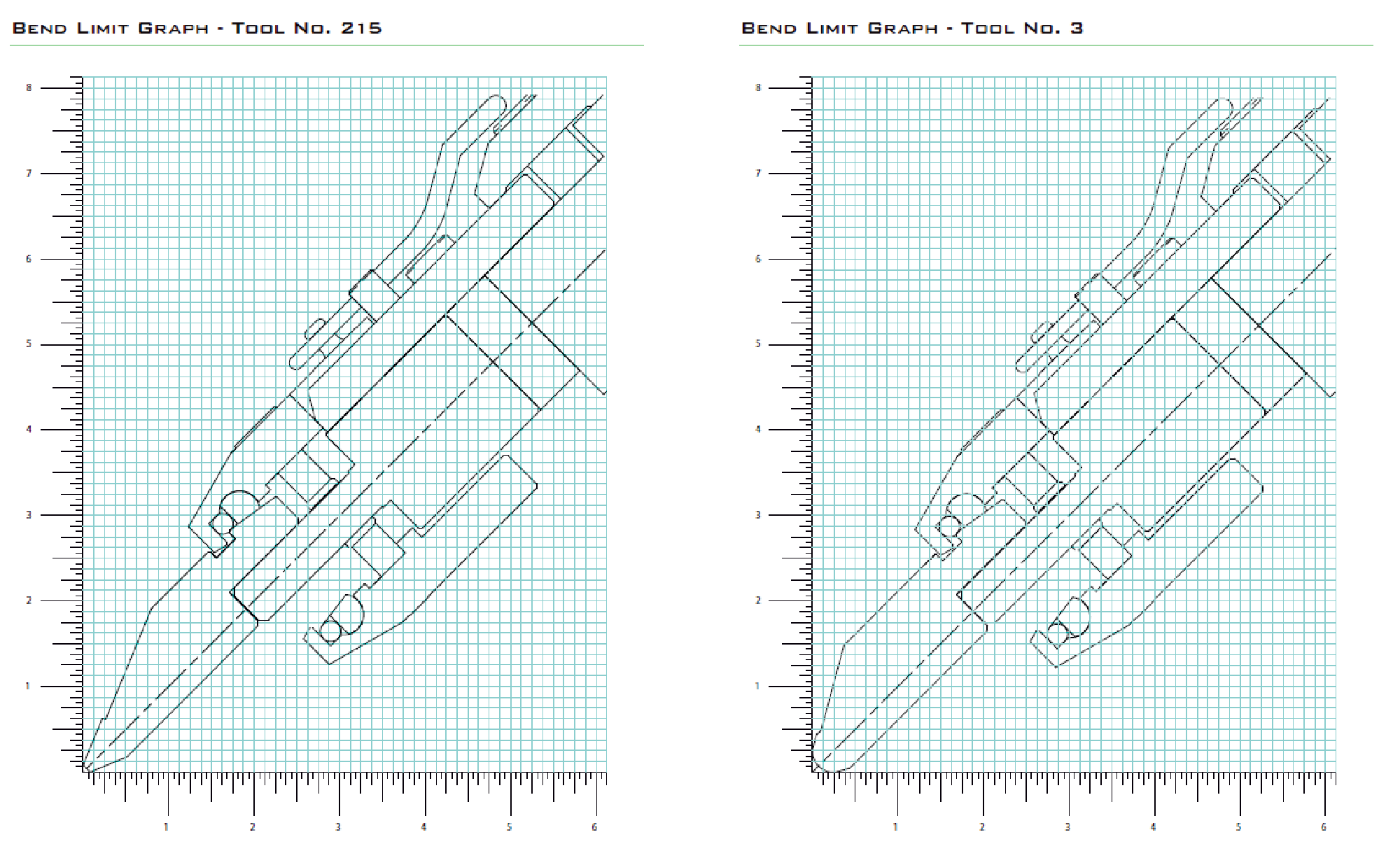
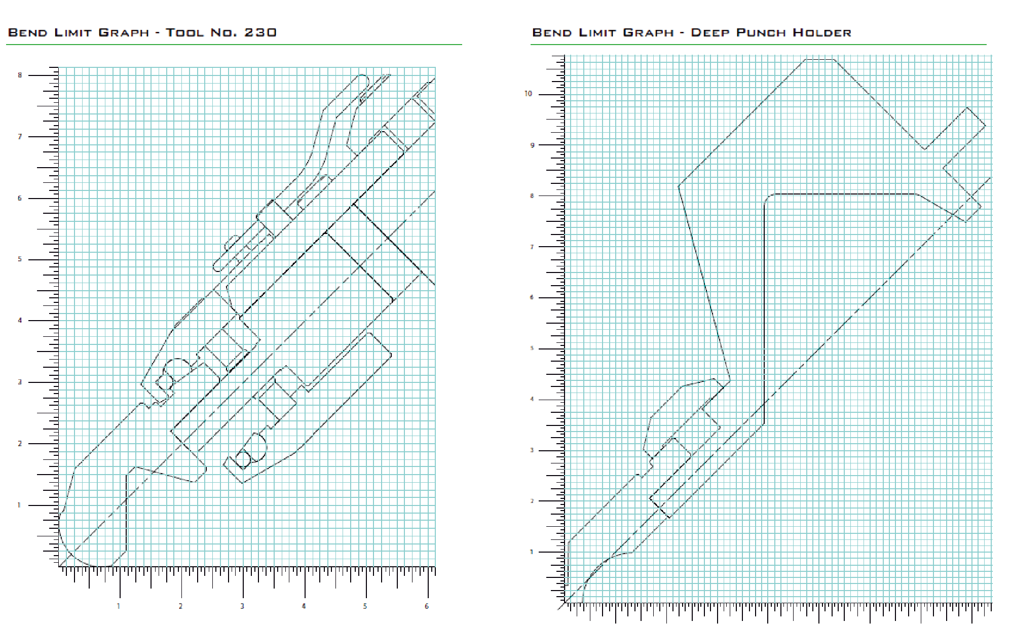
Forming (Bend Considerations)
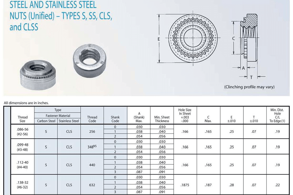
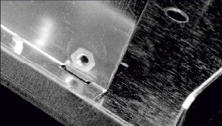
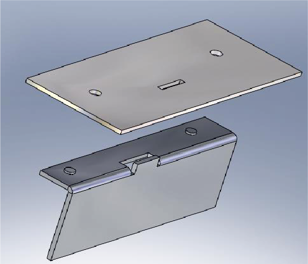
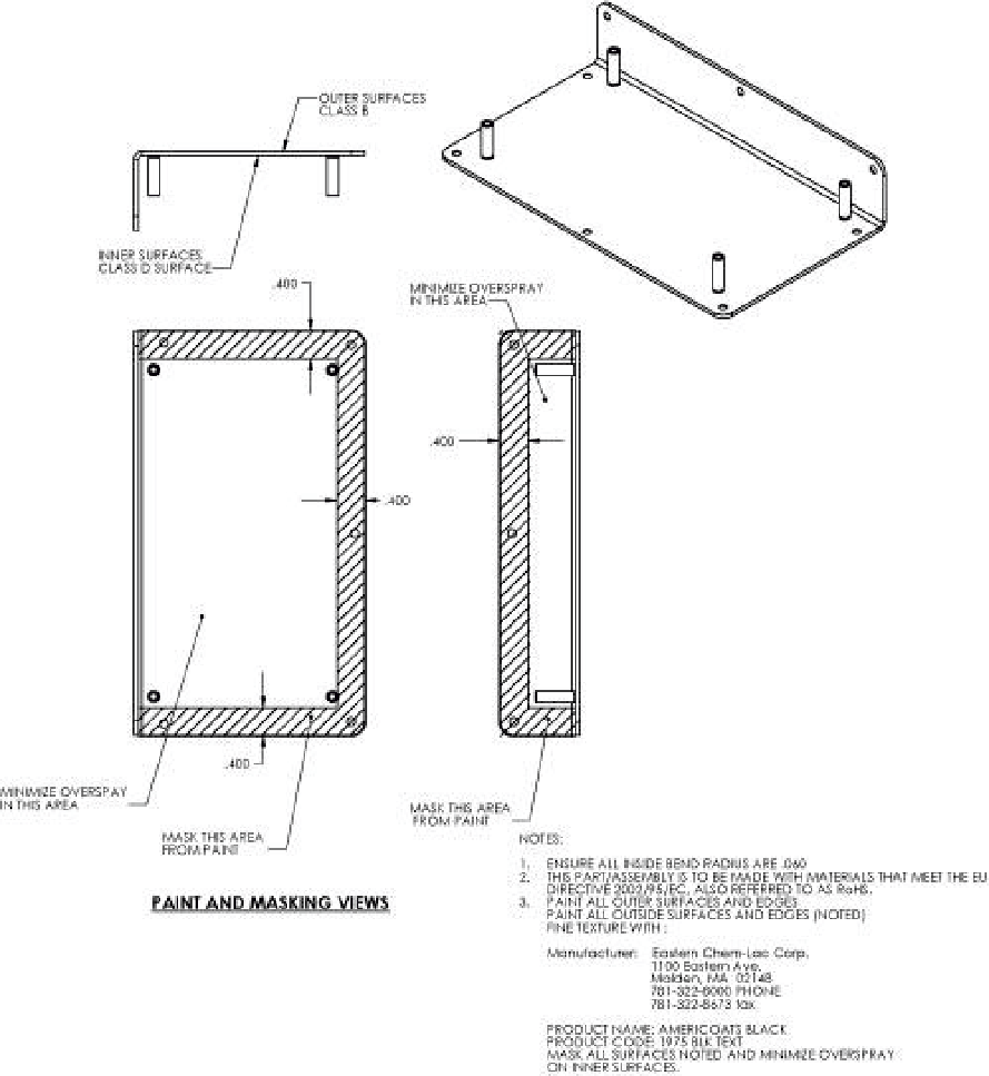
Inserting/Hardware Considerations
What is DFM?
Design for Manufacturing is the process of designing parts and assemblies to reduce complexity, lower costs and make them easier to manufacture. Every drawing submitted to Metal Works is reviewed by an engineer for DFM.
Inserting/Hardware Considerations
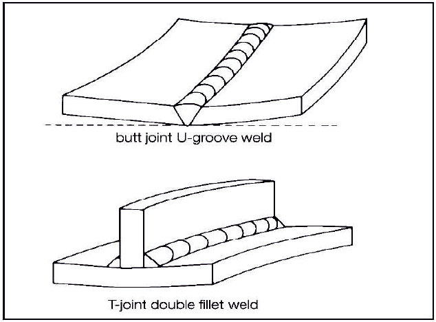
Weld and Grind Operations
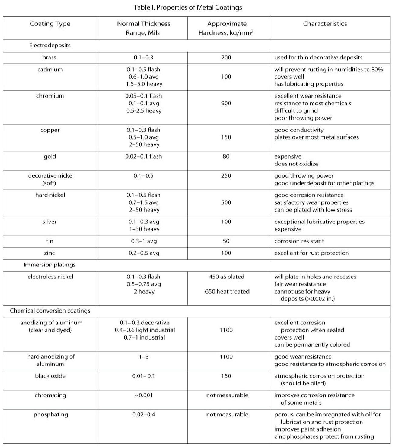
Material Thickness and Selection & Sheet Metal Finishing Options
Material Thickness and Selection (Cost Differences) & Finishing
Robotic Punching & Laser Cutting
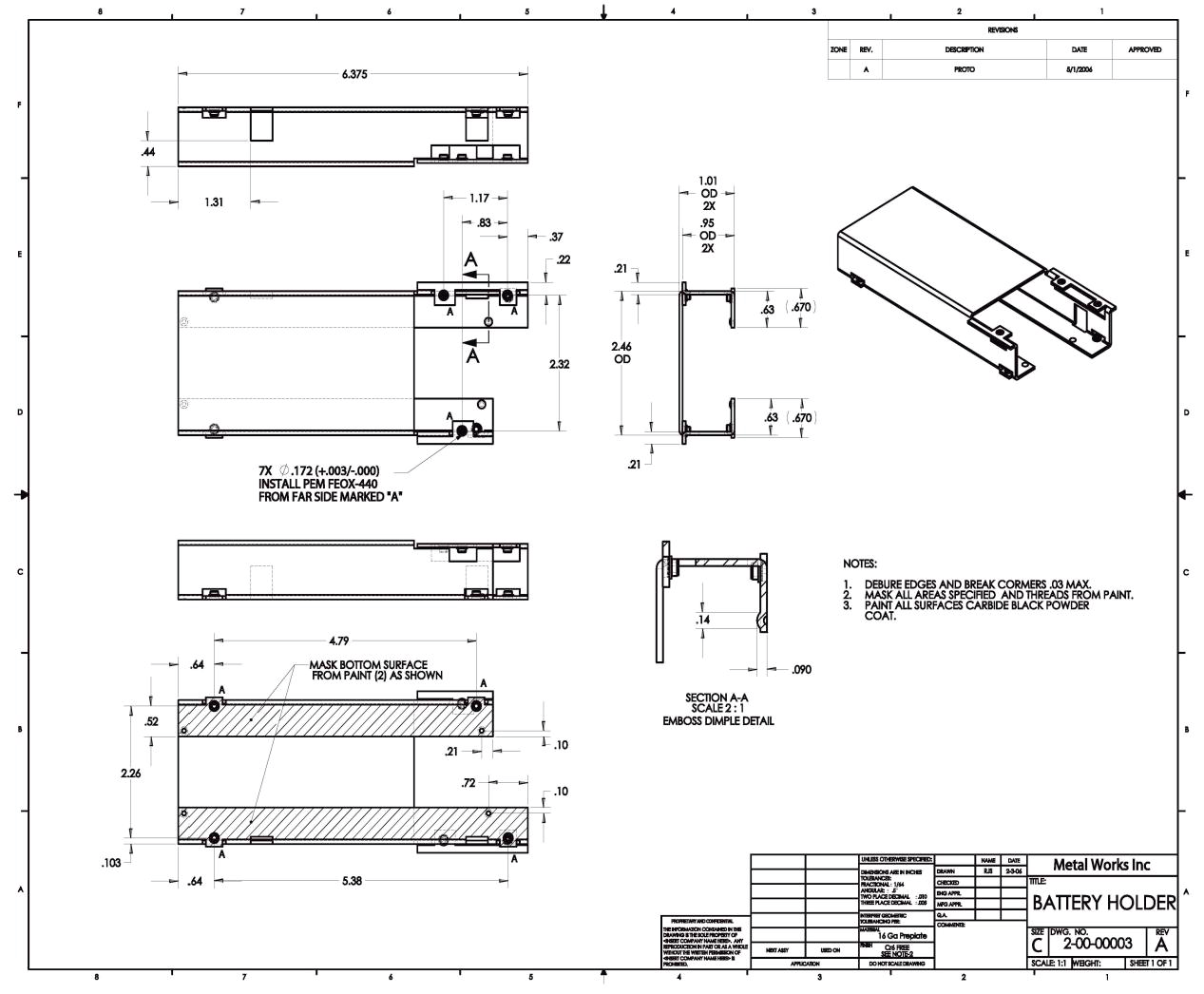
Drawing Information
Lorem Ipsum is simply dummy text of the printing and typesetting industry. Lorem Ipsum has been the industry's standard dummy text ever since the 1500s, when an unknown printer took a galley of type and scrambled it to make a type specimen book. It has survived not only five centuries, but also the leap into electronic typesetting, remaining essentially unchanged. It was popularised in the 1960s with the release of Letraset sheets containing Lorem Ipsum passages, and more recently with desktop publishing software like Aldus PageMaker including versions of Lorem Ipsum.
Part Number 1
Part Number 2
Part Number 3
Part Number 4
Part Number 5
Drawing Considerations (When detailing a part certain information is )
Robotic Punching and Laser Cutting
X
Y
A
B/1
B/2
1/A
1/B
1
1
2
2
2
2
3
3
3
3
4
4
4
4
5
5
5
5
Sheet Metal Tolerance Considerations (When dimensioning a part considerations for)
Forming (Bend Considerations)
Part Reductions with Special Features
Forming (Bend Considerations)
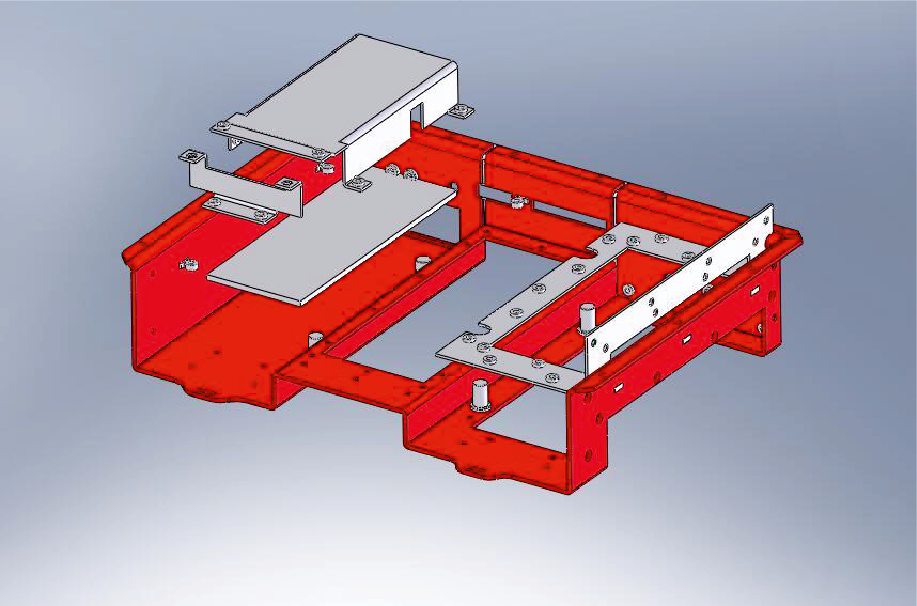
Part Combination, Symmetry and Common Thicknesses.
Design for Sheet Metal
Designing in common part thicknesses, Symmetry and combined features will enable parts to be nested together, reduce the number of parts and reduce assembly time. This helps reduce assembly cost.
Existing design
10 Sheet Metal Parts 2 Different materials 2 Different setups
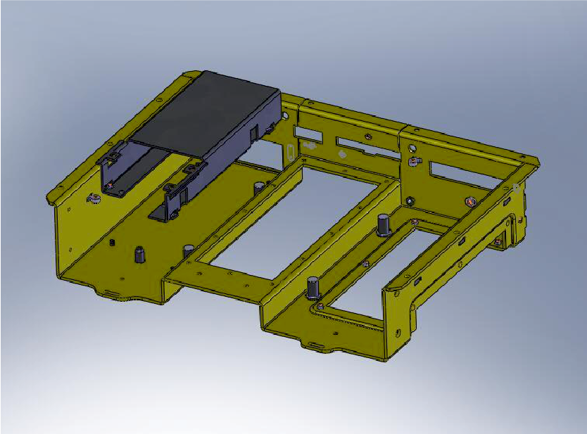
2 Different setups
6 Sheet Metal Parts Same Material Thickness 1 setup (Nested)
Forming (Bend Considerations)
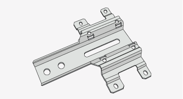
Minimum Cuts, Flanges and Notches
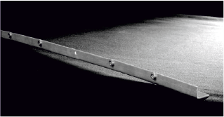
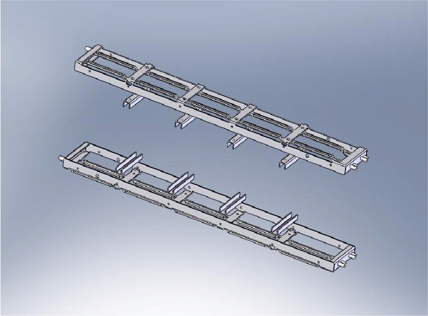
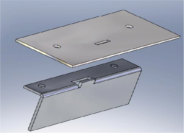
Riveting and Alignment Features
Critical features within an assembly require Increased awareness. Alignment feature as in welding are a cost effective way to reduce assembly time and ensure critical dimensions are met.